Leaving Antigua, W. I.

Saturday, January 29, 2011

Ready

Almost...

Everything is coming together.  The machine shop finished fabricating the engine rails last week, and we've put three coats of enamel on them.  They're so pretty that it's a shame to put them under the engine.  Speaking of which, the engine arrived in St. Martin yesterday.  The custom propeller is en route from the manufacturer in Canada.  We should have it by Monday.  We're ready to start work, except that we're waiting for dock space at the boat yard where we will do the work.  Soon come, as they say in the islands.

We considered loading the new engine in the cockpit and doing the work at anchor, but we need more electricity for our power tools than we can draw from our house battery bank without running the engine for a recharge, and we obviously can't run the engine until we install it.

Patience.  Soon come.


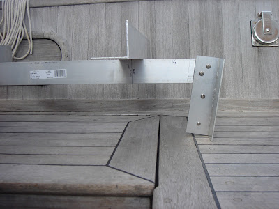
Starboard Engine Rail from back end

Port Engine Rail from back end


Still in the shiping crate

Friday, January 14, 2011

More Photos of the Engine Template

 The threaded rod is adjusted to 100 mm, the minimum height of the Yanmar supplied engine mounts.  The white board is just a work surface.
 The angle of the photo makes it difficult to see, but the centerline of  the shaft is about 11 mm below the plane of the mount feet (board surface).
Side view, showing the 7 degree angle of the transmission flange.

Thursday, January 13, 2011

To Help Pass the Time...

Top down view of engine template.  Red box is at front end.  Feet are optional.
 Side view, showing 7 degree angle of simulated transmission output flange.
 Seen from the front end.
Seen from the back end.  Simulated flange is square, with horizontal and vertical centerlines.


To help pass the time and sharpen our perceptions of spatial relationships, we built a three-dimensional template of the new engine today.  This was a 4-hour project, but it'll save a lot of time and energy later, as it is featherweight and embodies all of the critical dimensions of the new engine.  It is much easier to move around than a 400 pound diesel.  2x2 inch by 1/8 inch aluminum angle worked well for this, and when the job is done, it will be dismantled.  The short pieces of angle come in handy for all sorts of on-board projects.  We've normally kept a bit of it aboard anyway, and now we have plenty to make mounting brackets for all the odds and ends that will no doubt appear in connection with the new engine. 


There are four 1/2 inch holes where the engine mounts will go.  Rather than use the actual mounts, we'll use 1/2 inch threaded rod to simulate the mounts, because it will allow a much greater range of adjustment than the actual mounts will allow.  This is important at this stage, because we can set the template in place on the old beds and adjust the threaded rod to align the simulated coupling flange to the flange on the propeller shaft.  By subtracting the length of the threaded rod from the nominal height of the Yanmar engine mounts (100 mm), we can calculate how much of the existing bed we will cut off in order to put the engine in the proper vertical position.  Note that the corner of the longitudinal angle lies in the vertical plane of the centerline of the engine.  The simulated transmission output flange is set at a 7 degree angle to the axis of the engine, and it is the proper distance below the transverse angles which represent the engine mount brackets (111.5 mm, in the case of the 3JH5E with KM35A down angle transmission.)  All measurements are taken from Yanmar's engineering  drawings, which are readily available.

Wednesday, January 12, 2011

Waiting...

The last week has been a busy one on Play Actor.  The new engine is ordered, as is a new propeller, since the old one was left-handed and the new engine rotates in the opposite direction from the old one.  Besides that, the prop shaft speed and torque curve are different, requiring a different pitch for the propeller.  We settled on a final design for the engine bed modifications, and the drawings for the steel mounting rails are at a machine shop for fabrication.  We have aboard all of the components for the new exhaust, fuel, and cooling system plumbing.  The engine, prop, and rails should all be here at about the same time, so we're expecting to actually pull the old Volvo and start work in a week or ten days.

The drawing for the rails shows their configuration, which will minimize the amount of fiberglass work to be done on the engine beds.  The level of the old beds will be lowered for the aft half of their length, and the front end of the 4-inch wide plate will be through-bolted to the top of the bed, using the access hole in the inner side of the bed which is used for bolting down the front mounts of the Volvo.  A solid teak filler block will be glassed into place in the valley of the old bed to support the plate below the new front engine mount, which will be several inches farther aft than the Volvo front mount.  The aft part of the bed will be cut down to reduce the rake from 15 degrees to 8 degrees, and the remaining, hollow base of the bed will be filled with a custom cut, solid teak block, which will be fiber glassed in place.  The flange under the engine rail will then be through bolted to the bed at 90 degrees to the long axis of the bed.  Four 7/16" bolts will fasten each rail to the corresponding bed, transferring the thrust of the engine to the hull.  Two of the bolts will be oriented vertically, at the front end of the rail, and two will be horizontal and transverse to the long axis of the bed, through the flange in the aft half of the rail.